E-Stop Trigger Installation Guide
Category: Installation / Triggers
Overview
The E-Stop Trigger is a versatile device that measures whether your tool is running and provides power control through your tool's emergency stop circuit. It offers multiple installation options depending on your machine and which components are most accessible.
Installation consists of three primary steps:
| Step | What You're Doing | Options |
|---|---|---|
| Step 1 | Power the E-Stop Trigger | AC Mains connection, 110v-240v |
| Step 2 | Measure whether the tool is running | Option 1: Current Transformer (CT), or Option 2: Tool Running Signal |
| Step 3 | Control the tool's power | Wire inline with the E-Stop button or Off button |
Before You Begin
- The GRIT E-Stop Trigger runs on 110V–240V AC.
- Consult your tool's manual to identify the appropriate wiring points for Steps 2 and 3.
- Disconnect all power to the tool before beginning installation.
Step 1 — Power the E-Stop Trigger
Connect the AC Mains leads that come with your GRIT device into the contactor's terminals with the first two incoming hot wires.
Step 2 — Measure Whether the Tool is Running
Choose one of the two options below based on your machine and which components are most accessible.
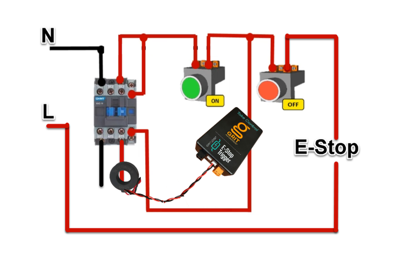
Option 1 — Measure with the Current Transformer (CT)
Use the CT (Current Transformer) included with your GRIT device to measure the tool's current draw.
Step 2a — Unscrew one of the load wires leading to the motor from its terminal.
Step 2b — Insert the wire through the middle of the CT.
Step 2c — Re-secure the wire in its terminal.
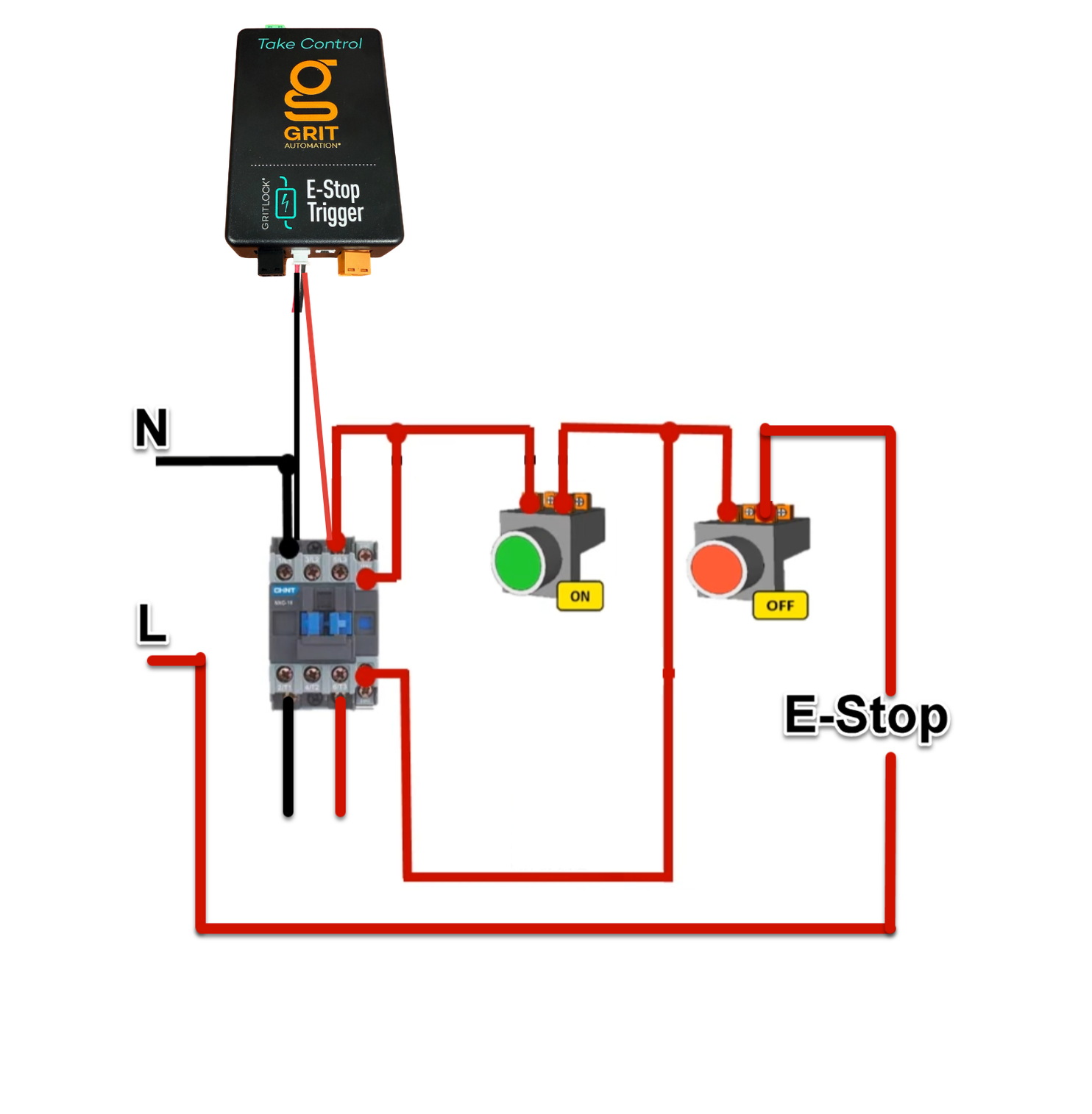
Option 2 — Measure with the Tool's Low-Voltage Running Signal
Use the removable Tool Running Signal terminal from the GRIT device to read your tool's running signal. This method wires the signal directly into the E-Stop Trigger rather than measuring current with the CT.
Note: The example below uses an AVID CNC. Consult the manual for your specific tool to locate the Tool Running Signal, if applicable.
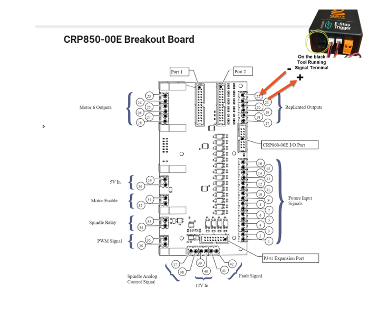
Step 2a — Locate the Tool Running Signal on your machine. On the AVID CNC, this is a 5V signal.
Step 2b — Insert the positive signal wire (terminal 21 on the AVID) into the right side of the black terminal on the GRIT device, marked with a +.
Step 2c — Connect the negative ground (terminal 22 on the AVID) to the left side of the same black terminal, marked with a −.
Step 2d — Plug the black terminal back into the E-Stop Trigger.
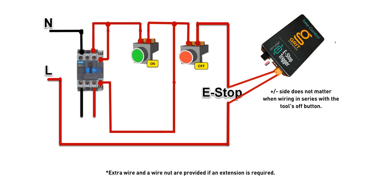
Step 3 — Control the Tool's Power
Wire the removable orange E-Stop contact from the GRIT device inline (in series) with the tool's emergency stop button or anywhere inline with the tool's Off button.
Note: +/− side does not matter when wiring in series with the tool's Off button.
Verify Your Installation
After completing all three steps, power the tool back on and confirm:
- The E-Stop Trigger powers up and connects to the GRIT mesh network.
- The Trigger correctly detects when the tool is running (check the power graph on the Trigger detail screen).
- The E-Stop contact successfully cuts power to the tool when the Trigger is locked.
For instructions on configuring the Activation Level and Power Profile for this tool, see: [Trigger Configuration: Activation Level and Power Profiles →]